Cam Timing
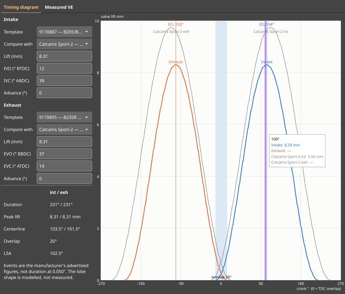
The cam timing tool (Tools → Cam timing) has two tabs that answer the same question from opposite ends. Timing diagram is specification: what a camshaft is supposed to do, drawn from its published events. Measured VE is measurement: what the engine actually swallowed, taken out of a log. Neither predicts the other, and that is the point — the diagram tells you what you fitted, the VE curve tells you what it did.
Timing diagram
Intake and exhaust are picked independently, because half the cam swaps people run are mixed — a T5 intake with a T7 exhaust, B234i with B202. Each side has its own template list containing only the cams for that side of the head.
Everything the template fills in is editable. A cam that is in no list at all — a regrind, something reground to a spec sheet a shop handed you — is typed straight into the four fields and the whole diagram follows.
| Field | Meaning |
|---|---|
| Template | Fills the fields below from a published cam. Editing them afterwards does not clear it |
| Compare with | Overlays another cam from the same side in grey, to compare shape against |
| Lift | Peak valve lift in mm |
| IVO / EVO | Opening event: intake ° BTDC, exhaust ° BBDC |
| IVC / EVC | Closing event: intake ° ABDC, exhaust ° ATDC |
| Advance | Turns the cam earlier in the cycle, as an adjustable cam gear does. Negative retards it |
The advance field exists because that is the one operation you cannot type in directly: advancing a cam 4° means the valve opens 4° earlier and closes 4° earlier, so IVO goes up while IVC goes down. Duration is unchanged. Get the sign wrong by hand and the diagram lies to you, so the tool does it.
Reading the graph
Crank angle 0° is TDC overlap — the top of the stroke between exhaust and intake, the only
point both cams are referenced to. Intake events are to the right of it, exhaust events to the
left. The shaded band is the valve overlap, the vertical lines are the two centerlines, and
hovering anywhere reads out the lift of every drawn cam at that crank angle (— means that
valve is shut).
What is derived, and how
| Value | From |
|---|---|
| Duration | open + 180 + close |
| Intake centerline (ICL) | duration / 2 − IVO, degrees ATDC |
| Exhaust centerline (ECL) | duration / 2 − EVC, degrees BTDC |
| Lobe separation (LSA) | (ICL + ECL) / 2, cam degrees |
| Overlap | IVO + EVC, crank degrees |
Two things to keep in mind before quoting a number off this page anywhere else:
- The events are the manufacturer’s advertised figures, taken at whatever reference lift they chose. They are not duration at 0.050", so they compare fairly against each other and unfairly against an American cam catalogue.
- The lobe shape is modelled, not measured. Nobody publishes lift curves for these cams, so the drawn lobe is a sin² hump spanning the advertised duration: symmetric about the centerline, zero lift and zero velocity at the quoted events. The events, duration, overlap and centerlines are real; the curve between them is a plausible shape, not that cam’s profile.
The cams
Specifications collected by 900aero.com. All figures in crank degrees and mm of valve lift.
| SAAB part | Fitted to | Side | Lift | Open | Close | Duration |
|---|---|---|---|---|---|---|
| 7509201 | B202 turbo 1984-85 | Intake | 8.65 | 10 | 56 | 246 |
| 7509219 | B202 turbo 1984-85 | Exhaust | 8.65 | 56 | 16 | 252 |
| 7560808 | B202 T16 1986-93 | Intake | 8.65 | 16 | 56 | 252 |
| 7560964 | B202/B212 1986-93 | Exhaust | 8.65 | 61 | 13 | 254 |
| 7561467 | B202i/B212 1986-93 | Intake | 8.65 | 16 | 44 | 240 |
| 9116690 | B234 1990-92 | Intake | 8.65 | 13 | 53 | 246 |
| 9116708 | B234 1990-92 | Exhaust | 8.65 | 50 | 16 | 246 |
| 9145632 | B204/B206 1994-2000 | Intake | 8.65 | 14 | 46 | 240 |
| 9145640 | B204/B206 1994-2000 | Exhaust | 8.65 | 44 | 16 | 240 |
| 9145657 | B234i 1994-2000 | Intake | 8.65 | 13 | 53 | 246 |
| 9145665 | B234i 1994-2000 | Exhaust | 8.65 | 48 | 18 | 246 |
| 9170887 | B205/B235R 1999-2001 | Intake | 8.31 | 12 | 39 | 231 |
| 9188855 | B205 1999-2001 | Exhaust | 8.07 | 34 | 14 | 228 |
| 9170895 | B235R 1999-2001 | Exhaust | 8.31 | 37 | 14 | 231 |
| Aftermarket | Side | Lift | Open | Close | Duration |
|---|---|---|---|---|---|
| Swedish Dynamics Red-series | Intake | 9.37 | 22 | 61 | 263 |
| Swedish Dynamics Red-series | Exhaust | 8.65 | 56 | 16 | 252 |
| Catcams Sport-1 (hydraulic) | Intake / Exhaust | 9.55 | 12 / 56 | 56 / 12 | 248 |
| Catcams Sport-2 (hydraulic) | Intake / Exhaust | 9.75 | 23 / 67 | 67 / 23 | 270 |
| Catcams Rally (hydraulic) | Intake | 10.95 | 28 | 64 | 272 |
| Catcams Rally (hydraulic) | Exhaust | 10.9 | 58 | 22 | 260 |
| Catcams Turbo (mechanical) | Intake / Exhaust | 11.3 | 18 / 58 | 58 / 18 | 256 |
| Catcams Race (mechanical) | Intake | 12.5 | 39 | 69 | 288 |
| Catcams Race (mechanical) | Exhaust | 11.95 | 65 | 35 | 280 |
The Swedish Dynamics row is the one place the source disagrees with itself: it prints 254° duration and 35° overlap where its own events give 252° and 38°. txlogger draws the events.
Three part numbers on that page (7518913, 9148305, 9148313) are listed without any timing figures at all and are therefore not in the tool — a name with no events draws nothing.
B207 (Trionic 8) has no templates on purpose. It runs intake CVVT, so its timing is a value that moves while the engine runs rather than a fixed spec.
Measured VE
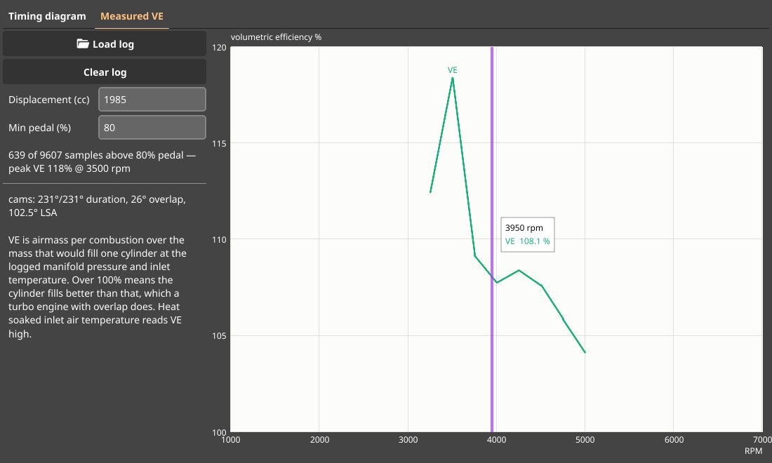
Volumetric efficiency is what a camshaft actually does to an engine: fill the cylinder better or worse at a given rpm. The ECU already logs everything needed to see it, so this tab needs no binary and no model — load a log and it computes, per sample:
        airmass per combustion (mg)
VE % = ────────────────────────────── × 100
        ρ × cylinder volume

ρ = manifold pressure / (287.05 × inlet air temperature)
Samples are filtered to at or above the pedal position you set, binned per 250 rpm, and the median of each bin with at least three samples is plotted. The curve therefore only spans the rpm your log actually pulled through at that pedal position — the screenshot above is a single WOT pull, which is why it starts at 3250 rpm.
| Input | Notes |
|---|---|
| Displacement | Whole engine in cc; the tool divides by four cylinders. 1985 for B202/B204/B205/B206, 2119 for B212, 2290 for B234/B235 |
| Min pedal | Pedal percentage a sample must reach to count. 80 % keeps it to full-throttle running; drop it to look at part load |
The channels it reads:
| ECU | rpm | Airmass | Pressure | Temperature | Pedal |
|---|---|---|---|---|---|
| T7 | ActualIn.n_Engine | MAF.m_AirInlet | ActualIn.p_AirInlet | ActualIn.T_AirInlet | Out.X_AccPedal |
| T8 | ActualIn.n_Engine | MAF.m_AirInlet | In.p_AirInlet | ActualIn.T_AirInlet | Out.X_AccPos |
Trionic 5 is not supported here: it logs no airmass, so there is nothing to divide by the reference mass.
The airmass channel is deliberately MAF.m_AirInlet, the mass the ECU measured per combustion
— not m_Request, which is the airmass the torque demand asked for and says nothing about
what the engine swallowed.
Reading the curve
- Over 100 % is normal on these engines. The reference is the manifold, not the atmosphere, so a turbo motor with overlap that scavenges well fills past the manifold density it was handed. The 118 % peak in the screenshot is a healthy 2.0 on boost, not a broken measurement.
- The shape is the useful part, not the absolute number. Compared before and after a cam change, on similar air temperatures, the difference is what the cam did.
- Heat-soaked inlet air reads VE high. The temperature sensor lags the real charge temperature after a hard pull, and a temperature that reads too high computes a density that is too low, which inflates VE. Back-to-back pulls at similar temperatures are worth more than one pull in isolation.
- On a T7 with the MAF disabled,
MAF.m_AirInletfalls back to the ECU’s pressure model. VE then measures that model rather than the engine.
The source lives in pkg/widgets/camtiming.